- Micropython and Thonny IDE
- Electronic components used
- A first programme ...
- Add on: Circuitpython
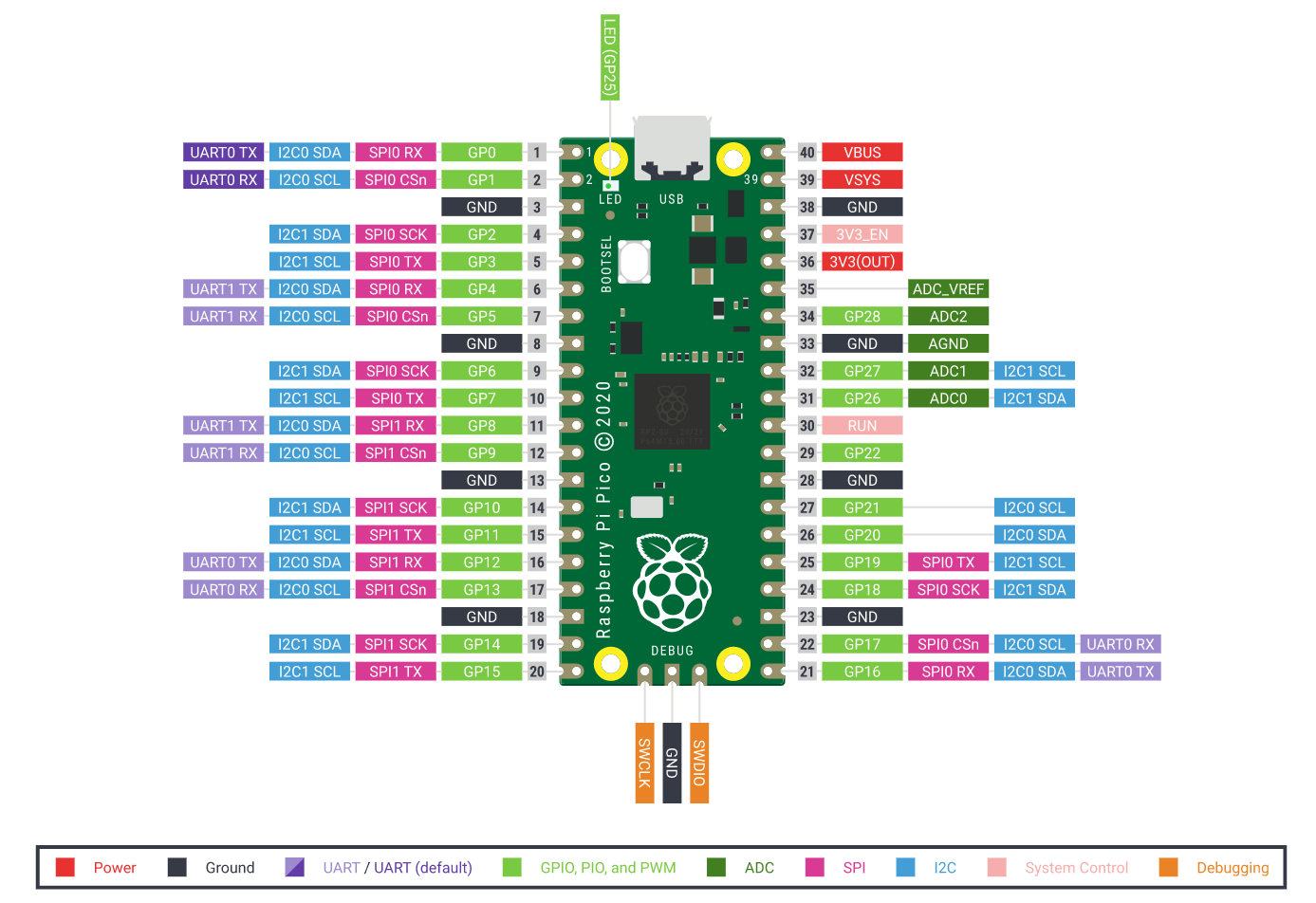
- Pico pinout
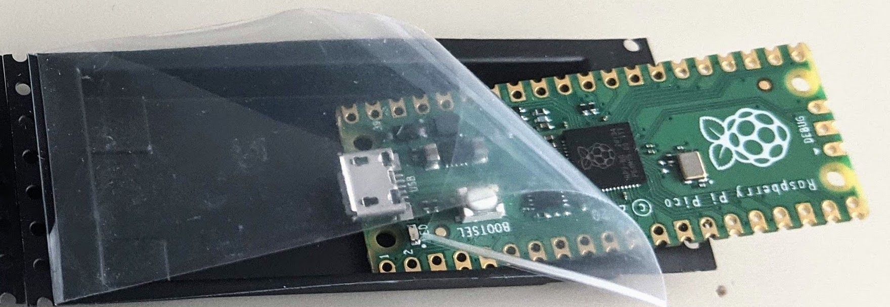
Eventually I got my hands on a Pico with Raspberry Pi’s first microcontroller chip (RP2040). Given that the board was only introduced in January 2021, the amount of documentation, example code and tutorials is truly astonishing.
So with this short blog post I want to see how quickly we can get a basic example running, including some input (ultrasonic distance sensor) and some output (OLED display), since I’ve used both components under Arduino, I had some sort of benchmark. The whole setup measured the distance between sensor and an object and translated this to a a constantly updating curve on the OLED display. There is still room for improvement, e.g.smoothing the data and slowing down the measurement would make the graphical output more attractive. Code for this example can be found here and there is also a version with an LCD display running on 3.3 V, so the wiring is basically the same. Also, as a pattern, as long as we can find the necessary drivers for the sensors we can generate similar setups for temperature and humidity sensors, air quality or light sensors - later we could also store the data on the Pico for further analysis / action ... the sky is the limit. The following video snipet demonstrates only the distance measurement.
This board is particularly interesting for its clock speed and memory (e.g. allowing for embedded machine learning usage), low power consumption (18 mA compared to 53 mA when using an ESP32), USB support for easy handling and all this at a very competitive price (≈4 €), similar to the ESP32. Andreas Spiess offers a comprehensive comparison between the Pico and comparable boards such as ESP32 or STM32 here: https://www.youtube.com/watch?v=cVHCllbN3bQ His final verdict for now is ‘no super obvious advantage’ beside the programable I/O. However, as we know, there is more to a board than mere functionality.
Micropython and Thonny
For this occasion I wasn’t looking for new or unique features. Even though the idea that directly programmable I/O can replace ‘bit banging’ in Python is very tempting, Commonalities with previous experiences are also key when considering this board as a serious contender for upcoming projects.
Getting started with installing the recommended Thonny IDE also delivers Micropython, a resources efficient implementation of Python 3.4, aiming to run under the constraints of microcontrollers. There is a fantastic free ‘Getting started online book’.
I haven’t yet experimented with Circuit Python the Adafruit fork of Micro Python. One of the main benefits is a quicker turnaround when programming going from 'edit-save-compile-upload-reset-run' to 'edit-save-run'. (Note: Using the UF2 bootloader which allows for programming boards over the Mass Storage Class (removable drive).
Electronic components used
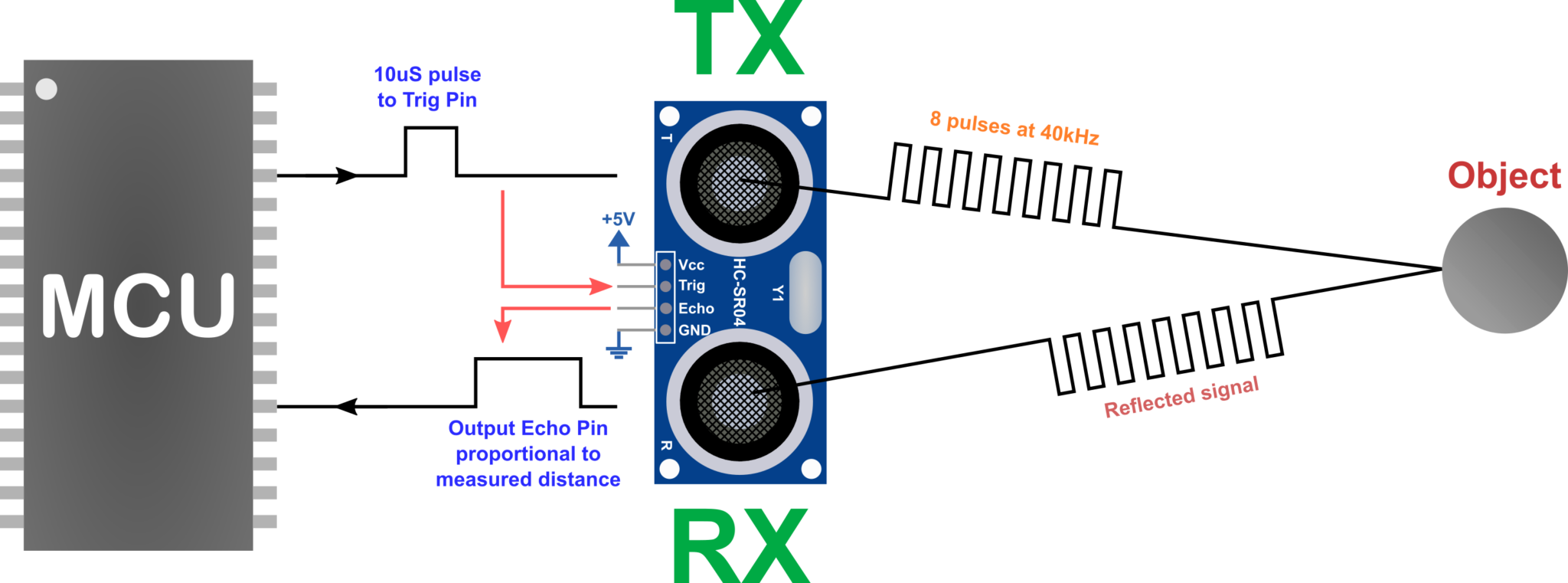
To get an input, we use the Ultraschall Sensor HC-SR04 which can measure distances between 2 cm and 4.5 meters. The sensor requires an input of 5V. The reliability of the distance measurement also depends on the surface of the object, i.e. a moving hand works most of the time but can also produce a lot of ‘noise’ in the measurements. Below a relative detailed overview of the signal flow.
The second component used is the OLED Display (64x48 pixels)
/ Driver: SSD1306 (I2C Address: 0x3C or 0x3D). With the following Pins for the I2C protocol:
| D1 mini | GPIO | Shield |
| D1 | 5 | SCL |
| D2 | 4 | SDA |
Wiring of components
The Trigger and Echo Pins of the sensor are connected to the Pico at GPIO3 (Pin 5) and GPIO2 (Pin 4). The OLED component is connected to I2C Pins (Pin 0=SDA, Pin 1=SCL) There is a Pico Pinout at the end of the post!
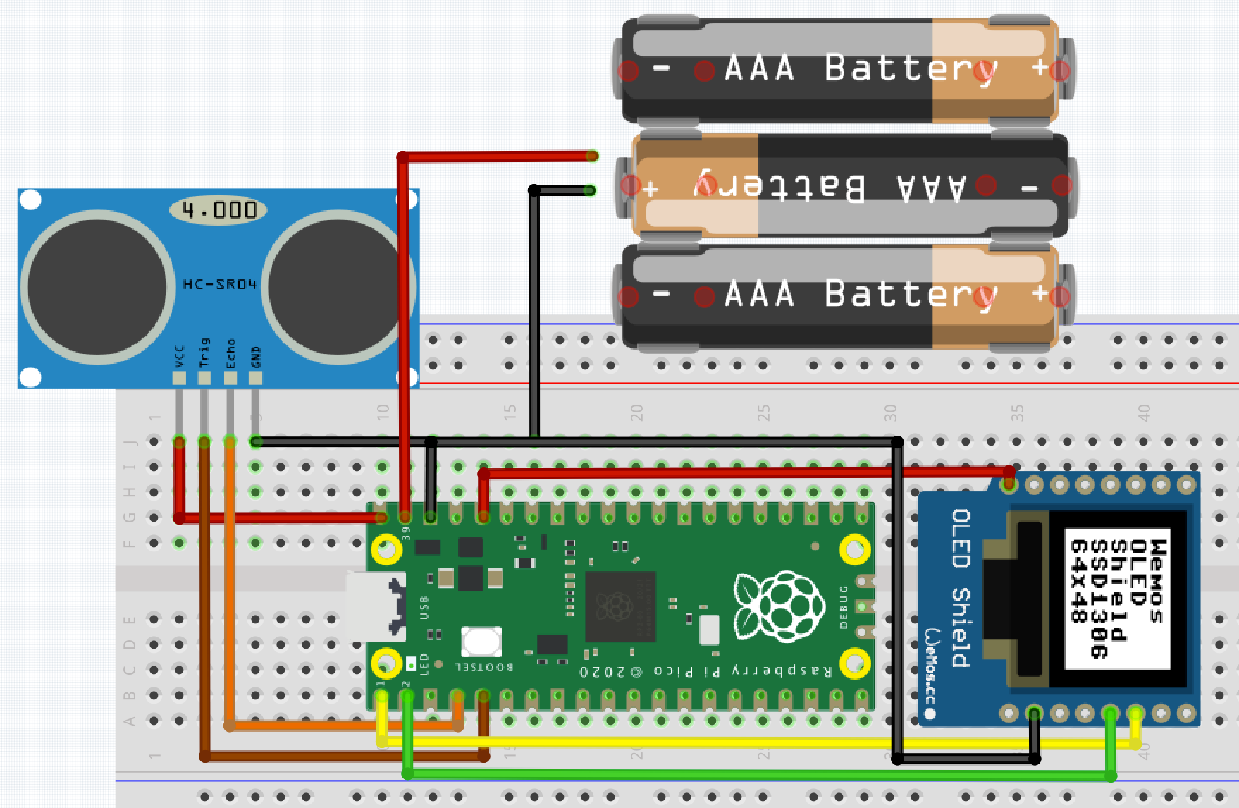
The Pico can be powered through USB -VBUS at Pin 40 or three AAA Battery – VSYS at Pin 39 (≈ 4.5 V). GP24 can be used to detect whether the Pico runs on battery or not.
Lastly, the fritzing part of the Pico is also an open source contribution.
A first programme
The moving wave form was inspired by an example visualizing sound using a microphone signal.
from machine import Pin, I2C
from ssd1306 import SSD1306_I2C
import utime
from hcsr04 import HCSR04

i2c = I2C(0, sda=Pin(0), scl=Pin(1), freq=400000)
oled = SSD1306_I2C(64, 48, i2c)
sensor = HCSR04(trigger_pin=3, echo_pin=2)
max_dist = 20 #the maximum distance helps scaling the curve on the display

while True:
    oled.fill(0) # clear the display
    for jj in range(64): # loop through horizontal display resolution
        dist_pt = sensor.distance_cm()
        if dist_pt > max_dist: dist_pt =max_dist
        plot_pt = (1-dist_pt/max_dist+0.0025)*46 # convert to OLED pixels
        if plot_pt > 47: plot_pt =47
        print(int(plot_pt))
        oled.text('.',jj,int(plot_pt)) # update x=jj with data point
    oled.show()
An entire collection of interface examples is provided here.
If we want to run the program without the IDE we need to name the main program ‘main.py’.
>>> import os
>>> os.listdir()
['hcsr04.py', 'ssd1306.py', 'ssd1306_test.py']
>>> os.rename('ssd1306_test.py','main.py')
>>> os.listdir()
['hcsr04.py', 'main.py', 'ssd1306.py']
Wrapping up
Following the maker paradigm of ‘ Low floor, wide walls, high ceiling‘ we could establish the low floor dimension, an afternoon and we could see parallels to the Arduino IDE and the way the board could be used within the ecosystem of existing sensors and drivers.
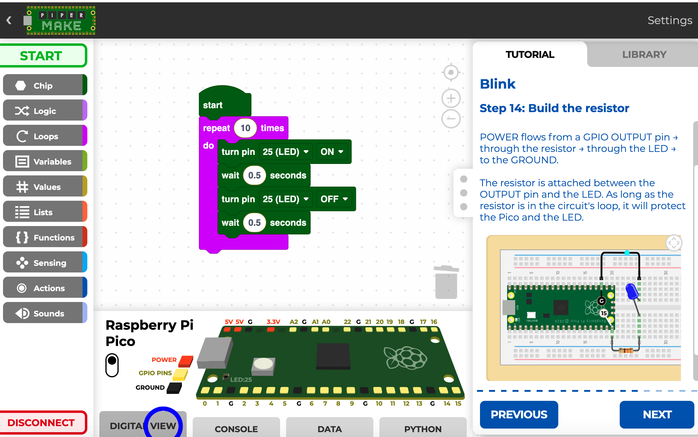
Similar to the MakeCode environment for Micro:bit or Calliope there is also a block-based programming environment for the Pico (https://make.playpiper.com/), which is entirely web-based, supporting application scenarios in schools. As always, it remains to be seen what blocks exist to program a wide variety of circuits or how easily those blocks can be added. For now, an intriguing idea are the integrated tutorials, leading through some first coding experiences.
Add on: Circuitpython from Adafruit
Adafruit’s Circuitpython and Micropython are mostly two different flavours of Python for Microboards. However, especially when starting with microboards, the explicit and detailed style of Adafruits’s learning system can be a highly valuable benefit.
As always the first action required is getting the right firmware onto the Pico. At the time of writing, 200 boards are supported, including the raspberry pico ord Arduino’s Nano 33 IoT.
As before, we need to keep the Pico’s ‘BootSel’ button pressed while connecting the board to our laptop, which makes the board appear as an USB drive. We then simply drag&drop the firmeware we just downloaded onto the Pico. The device automatically restarts and re-appears as CIRCUITPY. We can then use the Thonny IDE as before, if under ‘Run / Select Interpreter’ CircuitPython generic is selected.
There are a few naming conventions: All libraries which are not yet integrated into the firmware go into a folder called ‘lib’, such as our keypad library. Or ‘boot.py’ (or settings.py) runs only once on start up before USB is initialized. For example, the CPU temp code uses a boot.py file to make the Pico’s file system writable. That means, for changes in ‘boot.py’ to take effect, the board needs to be re-connected. Code.py (or main.py) is run after every reload (CMD + D) until it finishes or is interrupted.
Much more details can be found in either this introductory tutorial or the readthedocs.io pages.
The actual example is the use of a 4x4 keypad, as shown below.
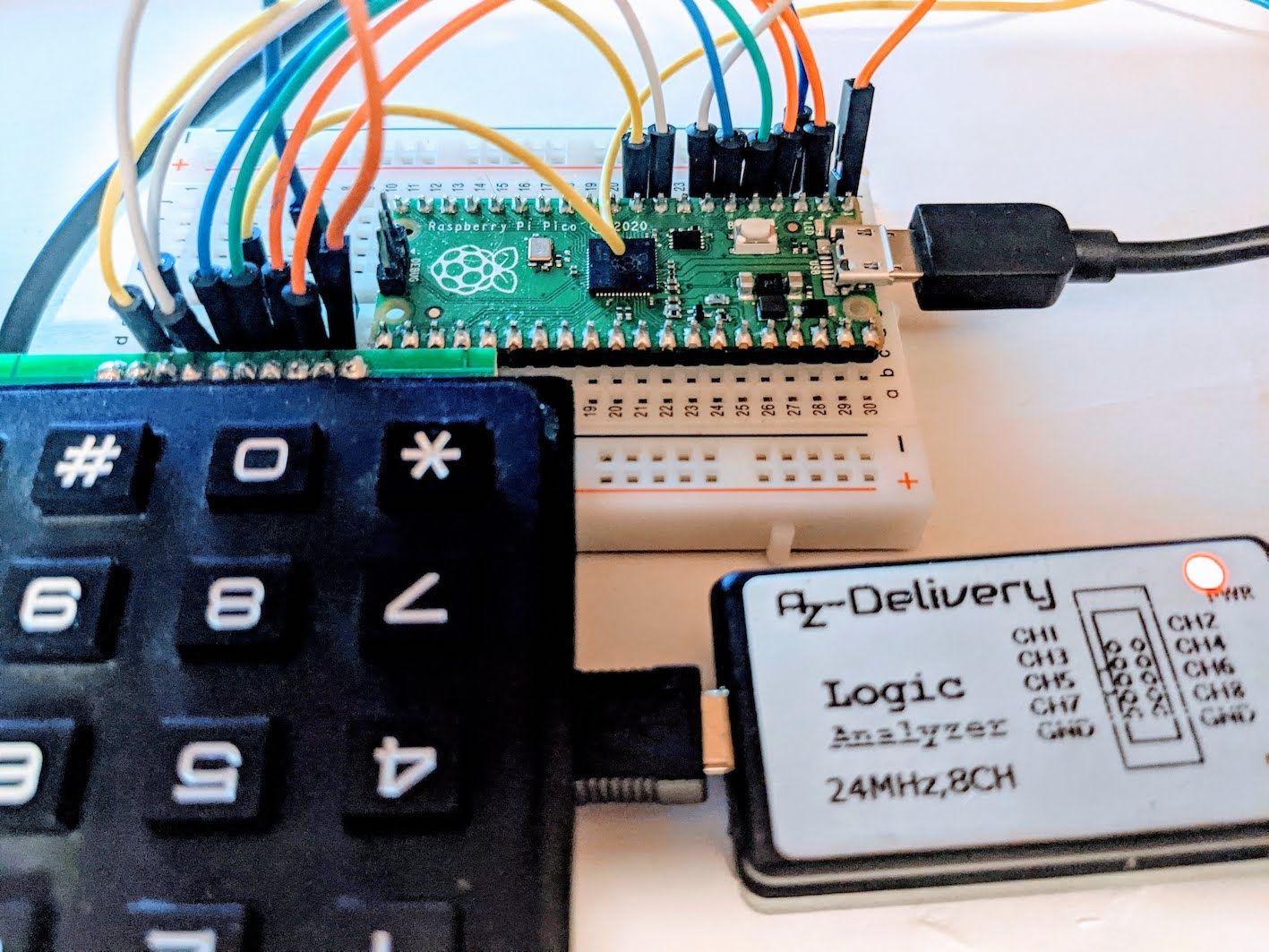
The keypad has 10 Pins (first and last one are not used), So we are left with 4 ‘column pins’ and 4 ‘row pins’. Hence every key is easily identified by a specific column-row pair (see below). For the example, I have connected the 8 pins to the first eight GPs of the Pico.
In the diagram above, the pins 1-4correspond to the columns while pins 5-8 correspond to rows. Determining if a particular button is pressed is done by programmatically changing the digital pins between input and output and reading pin state. Doing this across all possible pin combinations is referred to as a scan.
https://learn.adafruit.com/matrix-keypad/pinouts
The Code is then ...
import time
import digitalio
import board
import adafruit_matrixkeypad # needs importing to /lib/


# Extended 4x4 matrix keypad
cols = [digitalio.DigitalInOut(x) for x in (board.GP0, board.GP1, board.GP2, board.GP3)]
rows = [digitalio.DigitalInOut(x) for x in (board.GP4, board.GP5, board.GP6, board.GP7)]
keys = ((1, 2, 3, "A"), (4, 5, 6, "B"), (7, 8, 9, "C"), ("*", 0, "#", "D"))

keypad = adafruit_matrixkeypad.Matrix_Keypad(rows, cols, keys)

while True:
    keys = keypad.pressed_keys
    if keys:
        print("Pressed: ", keys)
    time.sleep(0.1)
Finally , for a larger project it would be good to check out ways to manage dependencies within the project. One option could by the upip package manager
Circuitpython Links
-
An explanation of CircuitPython Libraries
-
The latest bundle of libraries – compiled as well as as Python code – can be obtained here.
-
Github version of the code shown above: keypad example
RP2040 Chip features
• Dual ARM Cortex-M0+ @ 133MHz
• 264kB on-chip SRAM in six independent banks
• Support for up to 16MB of off-chip Flash memory via dedicated QSPI bus
• DMA controller
• Fully-connected AHB crossbar
• Interpolator and integer divider peripherals
• On-chip programmable LDO to generate core voltage
• 2 on-chip PLLs to generate USB and core clocks
• 30 GPIO pins, 4 of which can be used as analog inputs
• Peripherals
• 2 UARTs
• 2 SPI controllers
• 2 I2C controllers
• 16 PWM channels
• USB 1.1 controller and PHY, with host and device support
• 8 PIO state machine
Source: https://circuitpython.org/board/raspberry_pi_pico/